Schematic: LINK
STRIPBOARD LAYOUT
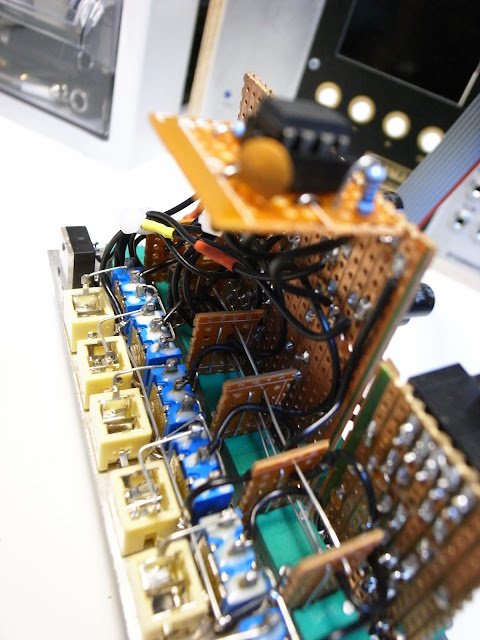
This module is based on Barton Musical Circuits Stereo Output.
I just added 2 more channels and mute switches on each channel.
And I slightly modified a headphone volume pot of the original circuit to control both stereo out and headphone out level.
I just added 2 more channels and mute switches on each channel.
And I slightly modified a headphone volume pot of the original circuit to control both stereo out and headphone out level.


AWESOME!! Many Thanks
ReplyDeleteNo problem! Hope it helps!
DeleteHi! First off, I'm sorry for my late reply and lack of explanation on this post. I'll update all my posts with more explanation sooner or later.
ReplyDeleteI used 9mm pots on this module. https://www.thonk.co.uk/shop/alpha-right-angle-t18/
Actually I bought them from aliexpress, though. I think those have same dimension.
Hope you enjoy your building!
Shouldn't the mute switches be arranged the other way, i e shorting the inputs to gnd? Anyway, this seems to be a decent and simple design and I understand that you cannot have too many mixers.
ReplyDeleteThanks for the heads up! Actuaclly I shorted the inputs to grounds, but I've not had any chance to correct the schematic and layout. I should do, but so many things to concern. Really sorry for that.
DeleteCould you let me know that is there any better way to mute signal besides shorting input to ground?
I think the best way is shorting inputs to GND. Else they could in a worst case pick up noise and stray signals.
ReplyDeleteAnother idea but with same result is to use shorting input connectors - no connector -> input grounded. Saves a toggle switch.
Appreciate!
DeleteI will correct the schematic as soon as possible.
Have a good day!